
![]()
Gas engine
Description of the biomass CHP technology based on gas engines
Combustion engines convert the chemical energy of the fuel into mechanical energy. The engine is connected to the generator shaft and drives the generator to produce electric energy. The fuel combustion takes place in one or more cylinders. The high pressure and temperature rise during the combustion process also permits relatively high conversion efficiencies for smaller plants. Excess heat from the engine cooling circuit, from the oil cooling system and from a heat exchanger for cooling the hot engine exhaust gases can be used for heat supply. The components necessary for the gas engine are often installed in a compact unit to form a block-type thermal power station and are encased for noise protection.
Gas engines are not limited to the use of natural gas. By appropriate adaptations, the engines are also suitable for the combustion of weak gases (for example pit gas, sewage gas or biogas) as well as product gases from gasification processes.
The chemical and physical properties of product gases differ from natural gas. In addition to the lower heating value, the reactivity (described by the laminar flame velocity) and the knock resistance (described by the methane number) of the product gas must also be considered. Accordingly, the engine operating parameters have to be adapted to the particular gas used.
Working principle and plant integration with product gas applications
The typical field of application of gas engines in biomass CHP systems is wood gasification systems with downstream gas cleaning and gas cooling stages in the small to medium power range (when using fixed bed gasifiers up to approx. 500 kWel; when using fluidized bed gasifiers up to approx. 3,000 kWel).
Figure 1 shows an overview of a typical wood gasification plant (stepped co-current fixed bed gasification technology) with a gas engine in the low power range and Figure 2 shows a photo with a gas engine in an encapsulated block design for a similar application.
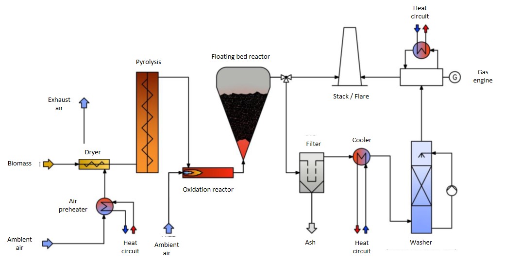
Figure 1: Schematic illustration of a biomass CHP plant based on a gasifier with gas engine
Source: Product information of the company Syncraft Engineering GmbH (A)
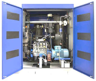
Figure 2: View of an enclosed gas engine as part of a biomass CHP plant based on gasification
Source: Product information of the company Spanner (D)
The product gas in the cylinder of the gas engine must be ignited by means of energy supply. This can be done either by conventional spark ignition (Otto engines) or by injection of a pilot jet.
Lambda-controlled Otto engines (at λ = 1) are operated with a stoichiometric fuel-air ratio. This allows the use of a three-way catalyst by oxidizing both, the CO in the exhaust gas to CO2 and the NOx to N2. As a result, very low emission values are achievable. However, the efficiency and the utilization of the cylinder volume are below those of turbocharged lean-burn engines and ignition jet engines. This has a negative effect on the economy, which is why these engines are rarely used in biomass gasification plants.
In the case of lean-burn engines (at approx. λ=1.6-2.0), the fuel-gas mixture is compressed in a turbocharger and then cooled in a mixture cooler, whereby the utilization of the cylinder capacity and the efficiency can be increased. However, an air excess is always present in these engines, whereby only CO but not NOx, can be catalytically converted in a downstream catalytic converter. Therefore, other measures must be taken to reduce NOx emissions. Such engines are used either as adapted natural gas engines or diesel engines converted to induced ignition in gasification plants quite frequently.
Ignition jet engines are diesel engines, which are adapted to the weak gas operation by the reduction of the injection quantity. The product gas-air mixture is introduced to the cylinder and compressed. Shortly before top dead center, a small amount of ignition oil (diesel or RME) is injected and hence the mixture is ignited. The proportion of the ignition oil in the entire fuel input into the engine is about 3-20% and can also be varied (up to 100%). These engines are generally operated with air excess and can be equipped with a turbocharger. Advantages result from a very robust operation, since e.g. a variation of the amount of ignition oil enables a quick reaction to altered product gas compositions and the possibility of switching to pure diesel operation contributes to increased failure safety and can improve the utilization of the engine. On the other hand, the increased complexity of the plant technology for the ignition oil supply as well as the tendency to increased CO and NOx emissions are disadvantages.
When using natural gas, the gas engines can be supplied directly with the fuel to generate electric energy. For the operation of the units, a corresponding cooling of the engine, the oil and the exiting hot exhaust gases is necessary. The waste heat can be used for space or process heat supply. If there is no use for the waste heat, the discharge takes place via an air cooler.
If the gas engine is connected downstream a gasification plant, the product gases produced during the gasification can be used for generating electricity and heat. For a good operation of the gas engines, particular attention must be paid to the long-term compliance to an acceptable product gas quality, to prevent the following problems:
- Tar deposits, especially in the gas control section as well as on the inlet valves and in the turbocharger and mixture cooler.
- Corrosion and acceleration of engine oil aging due to condensation of water with acidic product gas components.
- Increased wear due to alkaline metal particles in the product gas. If fine particles are not separated sufficiently in the gas cleaning, they lead to increased wear in the motor due to mechanical abrasion as well as to a reduced lifetime of the lubrication oil.
- Catalyst deactivation by small amounts of lead, zinc, potassium an sulphur compounds in the product gas and thus also in the exhaust gas.
For this reason, suitable product gas purification steps are needed upstream the gas engine in biomass CHP plants based on gasification, which reduce the overall efficiency due to higher heat losses.
Relevant technical data and efficiencies of gas engines
A key characteristic of gas engines is the medium pressure. This is around 13 bar for wood gas engines, while around 18 bar is possible in natural gas engines. A higher medium pressure, on the one hand, increases the efficiency and, on the other hand, reduces the investment costs, as the cylinder capacity of the engine is better utilized. The maximum possible medium pressure of a gas engine depends, among others, on the knock-resistance of the product gas. Since product gas compositions differ greatly in the process, the permissible medium pressure for each product gas (depending on the interaction of the knock drivers and inhibitors) also has to be determined individually. As a result of the lower medium pressure, a reduction in the achievable efficiency levels of approx. 4 percentage points results for product gas compared to natural gas. In product gas operation, maximum electrical efficiencies of approx. 36-39% are achieved with modern turbo-charged gas-fueled engines, depending on the product gas composition and power range, while the same engines achieve 40-43% with natural gas.
The electric power of gas engines currently available on the market is in the range of 20 - 10,000 kWel.
Emissions from gas engines operated with product gas
Combustion engines generally have some unavoidable fuel slippage due to geometric constraints (e.g. dead volumes, etc.) and the extinction of the flame on the cold cylinder walls (quench effect). For carbon monoxide, this is of the order of 1-1.5% (CO in exhaust gas to CO in the fuel gas). For carbon monoxide emissions from station heaters, limit values (approx. 500-1,000 mg / Nm³) are set in most European countries. If product gas from biomass gasification plants, which contains significant proportions of CO of about 20-30%, is used in gas engines, relatively high CO concentrations, which are typically in the range of 1,500-3,300 mg / Nm3, occur in the raw exhaust gas. The high CO emissions can be somewhat limited by reducing the air excess and the associated increase in the combustion temperature. However, the nitrogen oxide emissions increase as a result of the increased formation of thermal NOx. This is why, as a rule, secondary measures have to be taken to reduce CO emissions in order to comply with the official emission limits.
In the most commonly used turbo-charged Otto engines or spark-jet engines, oxidation catalysts or systems for thermal after-treatment can be used. The former can reduce the CO emissions by about 85% by catalytic oxidation with the air excess to CO2. However, they are very susceptible to impurities in the exhaust gas, such as heavy metal compounds (especially lead and zinc compounds) and alkali metal compounds (especially potassium compounds form together with alkaline earth metals such as calcium, deposit layers on the catalyst surface) which can lead to a significant reduction of the conversion rates.
An alternative to the oxidation catalyst is provided by thermal post-combustion systems. In this process, the exhaust gas is heated by a thermal storage mass so far that the CO gets oxidized in a reaction chamber without the presence of a catalyst. The cooling of the exhaust gas is then achieved by heat exchange with a second storage mass. From time to time, the flow direction is switched in order to charge or discharge the respective other storage mass. The advantage of this system is that catalyst poisons do not have any influence on the conversion and thus high service lives are possible. A moderate increase in investment costs and higher energy losses are disadvantages.
Nitrogen oxide emissions are generally composed mainly of the fuel NOx, which is formed from nitrogen compounds in the fuel, and thermal NOx, which is produced by oxidation of the air nitrogen at high temperatures. The formation of thermal NOx is mainly dependent on the combustion temperature. Increased combustion temperatures, as caused by a reduction of air excess and an increase in the medium pressure, lead to an increase in thermal NOx formation. In general, however, the amount of thermal NOx is relatively when combusting product gas in Otto engines. On the other hand, ignition jet engines tend to generate elevated thermal NOx due to higher combustion chamber temperatures. The formation of fuel NOx depends primarily on the content of nitrogen compounds in the product gas.
Since the formation of thermal NOx can only be influenced to a limited extent (lower efficiency at lower mean pressures, rising CO emissions with increased air excess), the removal of ammonia (NH3) and hydrogen cyanide (HCN) from the product gas is more relevant for limiting the NOx emissions of gas engines. Dry gas cleaning systems and systems with oil scrubbers (lower NH3 solubility in comparison to water) can result in disadvantages when using biofuels with high N contents. For chemically untreated wood fuels, which show relatively low N contents (about 0.1-0.2 wt.% w.b.), no special measures for NH3 removal from the product gas are required.